Grace Hopper developed the first compiler for a computer programming language.
- Github clone link
- Goals
- Overview
- Background
- Check Yourself
- Inputs, Output and Algorithm steps
- The Accelerators
- Step 0 : Generate gem5 configs for different accelerators
- Task 4: Cache-based MNIST (100 points)
- Task 5: DMA-based Accelerators (100 points)
- Report Submission
- Grading
- Acknowledgments
Github clone link
You can clone the repository using the following Github link.
Goals
- The purpose of this project is to have you implement a simple, yet extremely useful hardware accelerators.
- You will learn to use registers efficiently, write functions, use accelerator conventions for calling your functions,
- You will learn how to define datapaths, optimize them and connect them all up to create an SoC.
- You will learn how to move data between different accelerators.
This can be done in groups of up to 2 students for both graduate and undergraduates You can choose to either complete Task 4 (cache) or Task 5 (dma).
Overview
In this assignment, you will implement a simple neural network accelerator that can classify handwritten digits. You will implement three accelerators (ReLU, ArgMax, and matrix multiplication), and then use them to construct a Artificial Neural Net (ANN), which will be able to classify handwritten digits to their actual number! You will see that ANN inference accelerators can be simply implemented using basic numerical operations, such as vector inner product, matrix multiplications, and thresholding.
We will consider a simple 2 layer ANN, which takes in a 28x28 pixel image of a handwritten digit, and outputs a single number between 0 and 9 representing the predicted digit. The first layer of the ANN performs a matrix multiplication between the input image and a weight matrix, followed by a ReLU non-linearity. The second layer performs another matrix multiplication between the output of the first layer and another weight matrix, followed by an ArgMax non-linearity to output the predicted digit.
Background
At a basic level, a neural networks tries to approximate a (non-linear) function that maps inputs into a desired output. A basic neuron consists of a weighted linear combination of the input, followed by a non-linearity (e.g., a threshold). Consider the following neuron, which implements the logical AND operation:
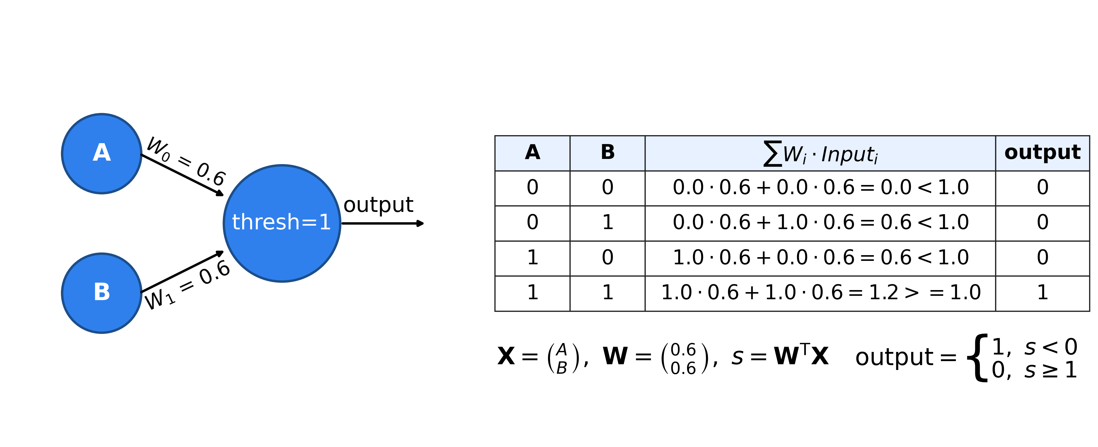
For A=0, B=0, the linear combination 0*0.6 + 0*0.6 = 0, which is less than the threshold of 1 and will result in a 0 output. With an input A=0, B=1 or A=1, B=0 the linear combination will results in 1*0.6 + 0*0.6 = 0.6, which is less than 1 and result in a 0 output. Similarly, A=1, B=1 will result in 1*0.6+1*0.6=1.2, which is greater than the threshold and will result in a 1 output! What is interesting is that the simple neuron operation can also be described as an inner product between the vector [A,B] and the weights vector [0.6,0.6] followed by as thresholding, non-linear operation.
More complex functions can not be described by a simple neuron alone. We can extend the system into a network of neurons, in order to approximate the complex functions. For example, the following 2 layer network approximates the logical function XOR (What is XOR?).
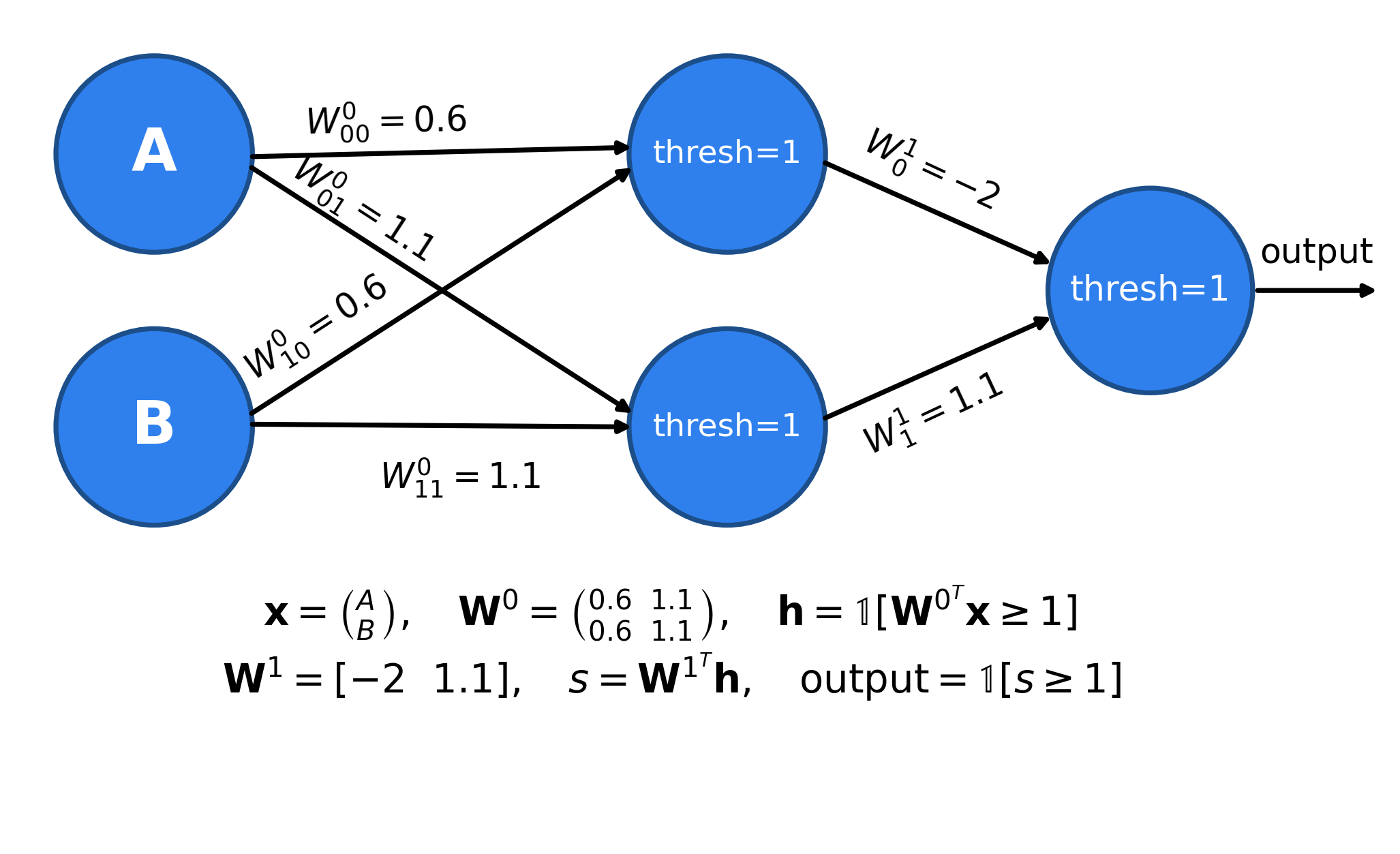
The above is a 2 layer network. The network takes 2 inputs, computes 2 intemediate values, and finally computes a single final output. It can be written as matrix multiplications with matrices $W^0$ and $W^1$ with thresholding operations.
The weights of the network were determined by training the network on pairs of correct inputs and outputs and changing the weights such that the error between the outputs of the network and the correct outputs is minimized. Learning the weights is called: Training. Using the weights on inputs is called “Inference”. We will only perform inference, and you will be given weights that were pre-trained on the correct input-output pairs. The process of training is outside the scope of this class, but if you’re interested in learning more about it, check out this Wikipedia page.
Handwritten Digit Classification
In this project we will implement a similar, but slightly more complex network which is able to classify handwritten digits. As inputs, we will use the MNIST dataset, which consists of 60,000 28x28 images containing handwritten digits ranging from 0-9. We will treat these images as flattened input vectors sized 784x1.
In a similar way to the example before, we will perform matrix multiplications with pre-trained weight matrices m_0 and m_1. Instead of thresholding we will use two different non-linearities: The ReLU and ArgMax functions, which are defined as follows:
def relu(x):
    return max(x, 0)

def argmax(x):
    return x.index(max(x))
The ReLU function is a non-linearity that sets all negative values to 0, and leaves all positive values unchanged. The ArgMax function returns the index of the largest element in the input vector. For example, if the input vector is [1, 3, 2], then the output of argmax will be 1, since the largest element is 3 and it is at index 1.
The overall algorithm for the neural network is as follows:
# In python matrix[m:n] has m rows and n columns.
def ANN(input):
  # Stage 1 Inputs: m0[128:784] * mnist_input[784:1], Output = [128:1]
  hidden_layer = gemm(m0, input).

  # Stage 2 Recall that relu can be performed in-place Inputs [128,1] = Output [128,1]
  relu(hidden_layer)

  # Input: [10:128] * [128:1] Output : [10:1].
  scores = gemm(m1, hidden_layer)

  # Input: [10:1] Output : [1:1] (scalar).
  result = argmax(scores)
  return result

First, we provide an implementation for the neural network in python. You can run it as follows:
$ cd $REPO
# python3 mnist_in_numpy.py <input_image> <m0_weights> <m1_weights>
$ python3 mnist_in_numpy.py $PWD/inputs/mnist/bin/inputs/mnist_input0.bin $PWD/inputs/mnist/bin/m0.bin $PWD/inputs/mnist/bin/m1.bin
Predicted label: 6
Check Yourself
- Look at the python code and identify the statements you will be accelerating.
- Have you gone over the gem5-SALAM lab (lab 2)?
- Do you know the difference in system model between DMA, Cache, and Streaming?
- Do you know how the SALAM-configurator (systembuilder) works? What is the output of
systembuilder.py? - How is the memory space of the accelerator laid out?
- How does host code detect accelerator has run to completion?
- How does the host code change between DMA and Cache?
- How does the accelerator datapath change between DMA/Cache and Streaming?
Inputs, Output and Algorithm steps
inputs/: the various input files and the two weight matrices used by our simple neural network.
The bin subfolder inside inputs/mnist contains the binary input files that you’ll load into the accelerator code, while the txt subfolder contains the plaintext versions (byte values) for debugging and calculating the expected output.
Within the bin and txt subfolders, you’ll find files for m0 and m1 which define the network, and a folder containing several inputs.
cd $REPO/inputs
$ ls mnist/bin/inputs
mnist_input0.bin mnist_input3.bin mnist_input6.bin
mnist_input1.bin mnist_input4.bin mnist_input7.bin
mnist_input2.bin mnist_input5.bin mnist_input8.bin

$ ls $REPO/inputs/mnist/bin/
inputs m0.bin m1.bin
ref/: Reference test cases for the operations we will accelerate (ReLU, argmax, matmul) and various examples of outputs for running the full neural network.
$ ls ./ref/
mnist
simple0
simple1
simple2
test_argmax.out
test_dot.out
test_matmul.out
test_relu.out
The traces display the out array of each of the stages in main. They include the outputs from each stage of main for verification:
$ ls ./ref/mnist/
mnist_input0.trace mnist_input3.trace mnist_input6.trace
mnist_input1.trace mnist_input4.trace mnist_input7.trace
mnist_input2.trace mnist_input5.trace mnist_input8.trace
Matrix File Format
Our matrix files come in two forms: binary and plaintext.The binary format is the one we will be using for all our programs as it is easier to read. The plain text version has been provided to help with debugging The usage is as follows:
We recommend the xxd command to open the binary file (DO NOT USE A TEXT EDITOR). You can find it’s man page here, but its default functionality is to output the raw bits of the file in a hex representation.
The first 8 bytes of the binary file represent two 4 byte integers. These integers are the number of rows and columns of the matrix. Every 4 following bytes represents an integer that is an element of the matrix, in row-major order. In this case each of the 4 bytes represents a vallue of the pixel There are no gaps between elements.. It is important to note that the bytes are in little-endian order. This means the least significant byte is placed at the lowest memory address.
To view the binary values of the file, run the following command:
$ xxd ./inputs/mnist/bin/inputs/mnist_input0.bin | more
# hit q to exit the viewer or (enter) to scroll down
Generating Your Own MNIST Inputs
Just for fun, you can also draw your own handwritten digits and pass them to the neural net. First, open up any basic drawing program like Microsoft Paint. Next, resize the image to 28x28 pixels, draw your digit, and save it as a .bmp file in the directory /inputs/mnist/student_inputs/.
Inside that directory, we’ve provided bmp_to_bin.py to turn this .bmp file into a .bin file for the neural net, as well as an example.bmp file. To convert it, run the following from inside the /inputs/mnist/student_inputs directory:
$ python3 bmp_to_bin.py example.bmp
This will read in the example.bmp file and create an example.bin file. We can then input it into our neural net, alongside the provided m0 and m1 matrices.
You can convert and run your own .bmp files in the same way. You should be able to achieve a reasonable accuracy with your own input images.
The Accelerators
In this assignment, all two-dimensional matrices will be stored as a one-dimensional vector in row-major order. One way to think about it is that we can create a 1D vector from a 2D matrix by concatenating together all the rows in the matrix. Alternatively, we could concatenate all the columns together instead, which is known as column-major order.
For a more in-depth look at row-major vs. column-major order, see this Wikipedia page.
The stride of a vector is the number of memory locations between consecutive elements of our vector, measured in the size of our vector’s elements. If our stride is n, then the memory addresses of our vector elements are n * sizeof(element) bytes apart.
So far, all the arrays/vectors we’ve worked with have had stride 1, meaning there is no gap betwen consecutive elements. Now, to do the row * column dot products with our row-major matrices that we’ll need for matrix multiplication, we will need to consider vectors with varying strides. Specifically, we’ll need to do this when considering a column vector in a flattened, row-major representation of a 2D matrix
Let’s take a look at a practical example. We have the vector int *a with 3 elements.
- If the stride is 1, then our vector elements are
*(a),*(a + 1), and*(a + 2), in other wordsa[0],a[1], anda[2]. - However, if our stride is 4, then our elements are at
*(a),*(a + 4), and*(a + 8)or in other wordsa[0],a[4], anda[8].
To summarize in C code, to access the ith element of a vector int *a with stride s, we use *(a + i * s), or a[i * s].
For a closer look at strides in vectors/arrays, see this Wikipedia page.
To test the subcomponents in we provide separate benchmarks for relu, argmax, and gemm. They exist in cache/{argmax, relu, gemm} for the cache-based model. For DMA, they exist in dma/{argmax, relu, gemm}. Each of these benchmarks has a host folder, which contains the host code, and a hw folder, which contains the hardware accelerator code. Your code goes in the top.c of the hw folder.
Next we will describe the three accelerators you will implement. We will be descussing how to implement them for the cache design. Details on what the files contain and how to run them are provided in the section after the description of the three tasks.
Task 1: ReLU
Implement our relu function to apply the mathematical ReLU function on every element of the input array. This ReLU function is defined as ReLU(a) = max(a, 0), and applying it element-wise on our matrix is equivalent to setting every negative value equal to 0.
Additionally, notice that our relu function operates on a 1D vector, not a 2D matrix. We can do this because we’re applying the function individually on every element of the matrix, and our 2D matrix is stored in memory as a row-major 1D vector.
v0 = [3, -42, 432, 7, -5, 6, 5, -114, 2]
ReLU(v0) = [3, 0, 432, 7, 0, 6, 5, 0, 2] (zero out all negative values)
We provide the skeleton code for you in cache/relu/hw/relu.c. You will need to fill in the top function. The top function takes in a 1D vector, and modifies the vector in place. This means that the input vector is modified, and the function does not return anything.
In order to pass data from the host to the accelerator, in the cache model, you can copy data to shared global memory, which the accelerator can access directly. To set the output, the accelerator code can write directly to a pre-defined region in global memory where the host can read the output. In the DMA model, you can use the DMA engine to copy data from the host to the accelerator, and back to the host.
Task 2: ArgMax
Near the end of our neural net, we’ll be provided with scores for every possible classification. For MNIST, we’ll be given a vector of length 10 containing scores for every digit ranging from 0 to 9. The larger the score for a digit, the more confident we are that our handwritten input image contained that digit. Thus, to classify our handwritten image, we pick the digit with the highest score.
The score for the digit i is stored in the i-th element of the array, to pick the digit with the highest score we find the array index with the highest value. Implement the argmax function to return the index of the largest element in the array. If there are multiple largest elements, return the smallest index.
Similar to the previous task, we provide the skeleton code for you in cache/argmax/hw/argmax.c and dma/argmax/hw/argmax.c (depending on which task you’ll choose to implement). You will need to fill in the top function. The top function takes in a 1D vector, and returns the index of the largest element in the vector. Input/output is handled in the same way as the previous task.
v0 = [3, -42, 432, 7, -5, 6, 5, -114, 2]
argmax(v0) = 2 (index of 432)
Just like relu, this function takes in a 1D vector. The index you’re expected to return is the index of the largest element in this 1D vector.
Task 3: Matrix Multiplication (gemm)
We will implement matrix multiplication as a collection of dot_products The dot product of two vectors a and b is defined as dot(a, b) = $\sum_{i=0}^{n-1} a_ib_i = a_0 * b_0 + a_1 * b_1 + \cdots + a_{n-1} * b_{n-1}$, where $a_i$ is the ith element of $a$. Notice that this function takes in the a stride as a variable for each of the two vectors, make sure you’re considering this when calculating your memory addresses. We’ve described strides in more detail in the background section above, which also contains a detailed example on how stride affects memory addresses for vector elements.
For a closer look at dot products, see this Wikipedia page.
e.g.,
v0 = [1, 2, 3, 4, 5, 6, 7, 8, 9]
v1 = [1, 2, 3, 4, 5, 6, 7, 8, 9]
dot(v0, v1) = 1 * 1 + 2 * 2 + ... + 9 * 9 = 285
What if we changed the length to 3 and the stride of the second vector v1 to 2, without changing the values in static memory? Now, the vectors contain the following:
v0 = [1, 2, 3]
v1 = [1, 3, 5]
dot(v0, v1) = 1 * 1 + 2 * 3 + 3 * 5 = 22
Note that v1 now has stride 2, so we skip over elements in memory when calculating the dot product. However, the pointer v1 still points to the same place as before: the start of the sequence of integers 1 to 9 in memory.
Now that we have a dot product function that can take in varying strides, we can use it to do matrix multiplication. Implement the gemm function to compute the matrix multiplication of two matrices. The matrix multiplication of two matrices A and B results in the output matrix C = AB, where C[i][j] is equal to the dot product of the i-th row of A and the j-ith column of B. Note that if we let the dimensions of A be (A_R*B_R), and the dimensions of B be (m * p), then the dimensions of C must be (n * p). Additionally, unlike integer multiplication, matrix multiplication is not commutative, AB != BA.
// A[n][m], B[m][p] .
// A - Base address, B - Base Address
// Unroll
for (i = 0; i<n; i++) {
// Note that for mnist p = 1 always for both stage 1 and 3
  for(j = 0; j<p; j++) {
// Dot product.
    for (k = 0 ; k < m; i++)
      c[i][j] = a[i][k] * b[k][j]
  }
}
You will need to store the data in row-major or column-major order as a contiguous array of elements to pass around from the host to the accelerator and the other way around. To calculate the index the ijth element in the matrix stored in a row-major order, you may use the formula i * num_cols + j, so A[i][j] will be accessed as A[i * num_cols + j]. Similarly, to calculate the index of the ijth element in the matrix stored in a column-major order, you may use the formula j * num_rows + i, so A[i][j] will be accessed as A[j * num_rows + i].
For a closer look at matrix multiplication, see this Wikipedia page.
We do not provide a skeleton for this task. It’s your job to implement the entire function from scratch. You will need to create a new “benchmark” in either the cache or dma directories and call it gemm. It will use the same structure as the two previous tasks.
Matrix multiplication takes in two input matrices and outputs a matrix. Hence, you need to allocate global memory that can be used by both the host and the accelerator. You will need to modify the config.yml to allocate space for the matrices. After invoking the SALAM-configurator, addresses for allocated spaces will be provided in the gemm_clstr_hw_defines.h file. You will need to use these addresses to access the matrices in the accelerator code.
You can hardcode small row-major matrices in the host code for testing. In the full MNIST classifier that you will build in the next sections, you will need to read the binary input and weight matrices.
Check yourself
- There are two different matrix shapes in GEMM. What are they ? What are the n,m,p factors for the Stage1:GEMM and Stage3:GEMM in MNIST.
- What is the total size of input and output (in bytes) of Stage1:GEMM and Stage3:GEMM
- If we wish to use a single hardware datapath for both Stage1:GEMM and Stage3:GEMM. What are the challenges? Hint: Think about the what happens if the total number of accesses made by an accelerator dynamically changes based on the input.
Step 0 : Generate gem5 configs for different accelerators
After generating py script fix OH and run it by the TA (Aditya)
You need to modify the config file to include different accelerator stages and configure scratchpads. For the cache based model, you will need to modify the cache/mnist/config.yml file. For the DMA based model, you will need to modify the dma/mnist/config.yml file.
The config files specify the accelerators and whether they need scratchpads. An example of an accelerator specification that uses a single scratchpad of size 128 bytes is shown below:
  - Accelerator:
    - Name: top # Name of the accelerator
      IrPath: cache/benchmark/hw/top.ll # Path to the IR file.
      Debug: False # Debug flag
      PIOSize: 25 # "Programmed" IO size (more on this next)
      InterruptNum: 68 # Interrupt number (always 68). Must be set only for the top accelerator
      PIOMaster: LocalBus # Always required for all accelerators
      LocalSlaves: LocalBus # Required only for the top accelerator
    - Var:
      - Name: spm1 # Scratchpad name
        Size: 128 # Scratchpad size in bytes
        Type: SPM # Scratchpad type
        Ports: 1 # Number of ports
Important things to note:
- The
PIOSizedesignates the number of bytes dedicated for PIO (Programmed IO). The minimum is 1 byte (stores the accelerator state). To send data to the accelerator top function through arguments (e.g.void top(int *arg1)), you need to set the arguments in the PIO space following the first byte. The PIO base is generated in the header file generated after running SALAM-configurator. For example, the PIO base for the accelerator we define above will be defined asTOPin c code in theBENCHMARK_clstr_hw_defines.hfile. The first argument is communicated through the addressTOP + 1, the second argument through the addressTOP + 1 + 8, and so on. - The first byte in the PIO space is reserved for the accelerator flags (e.g. a flag to check for idleness and a flag to check for completion).
- To check for idleness, you need to poll the first byte in the PIO space. If the value is 0, the accelerator is idle. If the value is 1, the accelerator is busy.
- To check for completion, you need to check the
DEVINTRflag (defined incommon/dma.h)
- Storage elements (SPM and RegisterBank) are defined by the
Varfield. TheNamefield is the name of the storage element. TheSizefield is the size of the storage element in bytes. TheTypefield is the type of the storage element. ThePortsfield is the number of IO ports of the storage element. After config generation, the base addresses of the storage elements will be defined in the defines header file. - Under the
hw_configfield in the config file, you need to list all the accelerators in the system as sub-fields for all of them to have the same instructions specifications. - DMA interrupt number is always 95
Fill config.yml with appropriate components
After filling the config file, you need to run the SALAM-configurator to generate the gem5 config file. The SALAM-configurator is located in the SALAM-configurator folder. For example, to run the SALAM-configurator on the cache/relu benchmark, you need to run the following command:
cd $REPO
$ SALAM-Configurator/systembuilder.py --sysName relu --benchDir "cache/relu"
Things to triple check in gem5-config/[$bench].py
- Do you have non coherent DMA? (in the configuration file)
- Do you have scratchpads? (If yes, double check memory map against the generated
.hfile) - Do you have top’s local connected? (see
multi_vector.pyin lab2 for a hint) - Do you have accelerators? (Is the scratchpad comm interface connected to scratchpad with many ports)
- Is accelerator’s acp port connected to the coherent xbar.
WARNING: DO NOT PROCEED TO SUBSEQUENT STEPS WITHOUT CHECKING
WITH TA ON GENERATED PYTHON FILES AND CONFIG
Baremetal input
The cache/mnist or dma/mnist benchmark will bring together everything you’ve written so far, and create a basic sequence of functions that will allow you to classifiy the preprocessed MNIST inputs using the pretrained matrices we’ve provided. You may need to allocate space when reading in matrices and computing the layers of the network, but remember we work with baremetal. Here, you will need to write a config file that defines multiple accelerators (gemm, relu, and, argmax) and specify the required scratchpad sizes.
Hint: Making a single accelerator that runs both GEMM stages can be hard due to the different size of matrices. So, in this assignment, you will define two different accelerators for the two GEMM stages and hardcode the size of input matrices.
The inputs are directly loaded in the global DRAM space SALAM-configurator/fs_template.py:line 153
Base address to load each file
0x80c00000
┌─────────────────────────┬──────────────────────┬───────────────────┐
│                         │                      │                   │
│  MNIST input (784 * 1)  │   M0  (128 * 784)    │   M1 (10 * 128)   │
│                         │                      │                   │
└─────────────────────────┴──────────────────────┴───────────────────┘
- Recall that the first 8 bytes contains the two 4 byte dimensions of the matrix, which will tell you how many bytes to read from the rest of the file. Additionally, recall that the binary matrix file is already in row-major order.
To supply the input and weight matrices, you should use the --input, --m0, --m1 switches to the gem5 command. The following is an example of how to run the MNIST classifier with the first input and weight matrices:
# In this assignment, you should be using clang-11.
# To load it on the CMPT750 lab machines, run the following command:

$ source /data/.local/modules/init/zsh
$ module load llvm-11
$ clang++ --version
clang version 11.1.0 (ssh://git@github.com/llvm/llvm-project 1fdec59bffc11ae37eb51a1b9869f0696bfd5312)

$ export M5_PATH=/data/gem5-SALAM-v2
$ export LAB_PATH=$PWD
$ mkdir -p out_mnist
$ export OUTDIR=out_mnist
$ export CROSS_COMPILE_DIR="/usr/bin"

$ cd $LAB_PATH/cache/mnist
$ make

$ cd $LAB_PATH
$ $M5_PATH/build/ARM/gem5.opt \
  --outdir=$OUTDIR gem5-config/fs_mnist.py \
  --mem-size=8GB --kernel=$LAB_PATH/cache/mnist/host/main.elf \
  --disk-image=$M5_PATH/baremetal/common/fake.iso \
  --machine-type=VExpress_GEM5_V1 --dtb-file=none \
  --bare-metal --cpu-type=DerivO3CPU \
  --input=inputs/mnist/bin/inputs/mnist_input3.bin \
  --m0=inputs/mnist/bin/m0.bin --m1=inputs/mnist/bin/m1.bin \
  --accpath=$LAB_PATH/cache --accbench=mnist --caches \
  --l2cache --acc_cache > $OUTDIR/debug_trace.txt
Task 4: Cache-based MNIST (100 points)
BASE Folder: cache/
Source
# inside the `cache` folder:

relu:
defines.h  host  hw  Makefile config.yml configs

argmax:
defines.h  host  hw  Makefile config.yml configs

# Common interface calls. Typically you should not have to read these files.
# Apart from knowing what the interface calls do.
common:
dma.h  fake.iso m5ops.h  Makefile  queue_dma.c  queue_dma.h  syscalls.c  syscalls.o

# Your main task is to implement the following accelerator
mnist:
defines.h  host  hw  Makefile config.yml configs
Each of the accelerators are organized in the following manner
| host | Contains the host code. TODO: FILL main.cpp |
| hw/*.c | TODO:Datapath definitions for hardware accelerators |
| config.yml | TODO:. Configs for each of the accelerators. Fill accelerator and scratchpad. |
Check yourself
WARNING: DO NOT PROCEED IF YOU ARE UNABLE TO ANSWER ALL OF THE QUESTIONS BELOW.
- What n,m,p dimensions for stage1:gemm and stage3:gemm?
- Read the config files. What is the MMR (memory-mapped) argument register addresses for each of the accelerators mnist
mnist/hw/hw_defines.h? - What is the address range of input, m0, and m1 matrices in the DRAM? What is the size of the matrices in bytes ?
- What is the address range read by the gemm accelerator?
- How many arrays do you need to allocate space for
Hint: Note that Relu can modify in place - How many bytes do you need to allocate for the hidden_layer and scores matrix?
- If you unrolled the m0 matrix by 128. How many multipliers would you need to multiply m0 and input. How many cycles would it take to calculate a single element in hidden_layer?
mnist/host/main.cppDraw the memory layout. You will need temporary matrices to hold intermediate results, the hidden_layer, scores, and final resultmnist/hw/source/top.cInvoke the accelerators in sequence, setting up pointers to the main memory.mnist/hw/source/{relu.c, gemm1.c, gemm2.c, argmax.c}Implement the accelerator functions.
REPORT
Include the following in your report:
- Embed config.pdf in your report and mark up your design clearly
- Describe your architecture. which ports were connected and why
- Explain how your host code invokes the accelerators
- Explain how your top accelerator orchestrates the execution of the other accelerators
- If we wish to use a single hardware datapath for both Stage1:GEMM1 and Stage3:GEMM3. What are the challenges?
- Do you expect performance improvement from cache-based model over the DMA model? Explain why.
- Vary the unroll factor of the
m(outer) loop inmnist/hw/gemm1.cfrom 4,8,16. - Vary the cache size from 32K, 64K, 128K, 256K,1M in
gem5-config/mnist.py:line 27. cache size can be supplied as a parameter to_connect_cachesusing thecache_sizeargument.
To unroll a loop using clang, you can add the following line before a loop:
  #pragma clang loop unroll_count(4)
  for (int i = 0; i < N; i++) {
    // ...
  }
This unrolls the loop by a factor of 4. You will need to experiment with different unroll factors and cache sizes and plot the performance, stall cycles, and energy next.
| Metric | Description |
|---|---|
top:Runtime debug-trace.txt |
Total execution time |
gemm:Rutime debug-trace.txt |
gemm execution time. WARNING: For each invocation of gemm you will see a stat dump |
relu:Rutime debug-trace.txt |
relu execution time. WARNING: For each invocation of gemm you will see a stat dump |
argmax:Rutime debug-trace.txt |
argmax execution time. WARNING: For each invocation of gemm you will see a stat dump |
- Plot 1 Performance Create a scatter plot for top:runtime for combination of unroll factor and cache size [4,8,16] x [32K,64K,128K,256K,1M] 20 simulation points. Which configuration performs best? Why?
- Plot 2 Stall Cycles Plot a stacked bar plot. Stall and Compute cycles (Runtime - stall), for each accelerator (gemm,relu,argmax) for the unroll factors (64,128) and cache sizes (32K, 64K, 128K) Which configuration minimizes stall cycles? Why?
- Plot 3 Energy
Calculate the cache energy as follows:
number_of_cache_accesses * cache_energy + sum(total_power_i * cycles_i)
Calculate the op energy as follows
\# of ops * energy per op
THe total number of cache accesses can be extracted from the generated stats file. We are interested in the accelerator cache accesses (hits + misses). They are under system.mnist_clstr.cluster_cache.demandHits::total and system.mnist_clstr.cluster_cache.demandMisses::total. Cache energy is a function of the size and is given in the table below. The total power (static + dynamic) and the number of cycles are given for each accelerator component in the debug-trace.txt file.
| Config | Energy |
|---|---|
| 32K | 22pj |
| 64K | 24pj |
| 128K | 27pj |
| 256K | 30pJ |
| 1M | 32pj |
Optmization: One of the matrix input can be held in registers entirely.
To reduce the cache accesses one of the matrices in gemm can be held in registers to prevent repeated accesses to the cache. For example, you can load the input matrix in a register bank.
A RegisterBank is defined similar to a scratchpad in the config file (Type: RegisterBank) and then it will be accessed normally through memory addresses (memory mapped) and it has the same interface as a cache. The base address of the RegisterBank will be provided in the mnist_clstr_hw_defines.h file.
- Plot 4: With RegisterBank. 1M cache, 256 unrolling factor. Plot the energy (calculated similar to previous task) and cycles with and without the register bank optimization
Task 5: DMA-based Accelerators (100 points)
BASE Folder: dma/
The cache-based model permits the accelerators to work with data in global DRAM. This increases the energy cost of every memory access in the accelerators (even if they are cached in the cluster cache). We introduce a local scratchpad for each accelerator to make data accesses more efficient. However, an important constraint is that accelerators can only touch and work with data locally stored in their scratchpad. This makes it challenging to support Stage1:gemm and Stage3:gemm in the same hardware since they work with matrices of entirely different shapes.
- Stage1:gemm Inputs: m0[128:784] * mnist_input[784:1], Output = [128:1]
- Stage3:gemm Input: [10:128] * [128:1] Output : [10:1].
This means we will have to create two different gemm accelerators in the cluster. Model 1 in figure below.
- The size of the scratchpad. To calculate an element/row in the hidden layer we need 784 ints (from the m0 matrix), 1 int (for result). The 784 ints of the input matrix are shared between all the rows. The total scratchpad required for calculating N rows of hidden layer in a batch is.
Model 1: 1 Tile
In the baseline DMA model we assume that the scratcpad can hold the entire working set of all the required input and output matrices. i.e., 1 Tile encompasses the entire matrix. Here, once the data is in the scratchpad you are only limited by the number of ALUs used for the computation.
The stage1:gemm is most arithmetic intensive and we will be exploring multiplier utilization for this stage.
You can explore this using the manually unroll of the outer loop for (i = 0; i<n; i++) { . What is n for Stage1:gemm?
- The number of multipliers/adders/subtractors that controls how many multiplications and additions can be performed in a cycle.
Check yourself
- How many multipliers does the inner loop
mrequire in stage1:gemm and stage2:gemm (assume its fully unrolled). - If unroll factor 10. How many multiplipliers is required ? (assume m loop is fully unrolled)
- What is the working set (number of bytes for input a
single elementin output) for stage1:gemm, stage2:relu, stage3:gemm and stage4:argmax? e.g., Stage1:gemm. To calculate hidden_layer[0][0] requires 1 row from the m0 (7844), entire mnist_input (7844), and 4 bytes for result. Note that mnist_input is shared/reused for calculating entire all hidden_layer[0:128][0].
Model 2: 1 Tile Merged accelerators
Note that relu and argmax can be folded into their previous stages as they are pure functions that can run on each element of the matrix independently. This means we can eliminate the DMAing/scratchpads for relu and argmax.
Select Model 2
Report
- Fix number of multipliers to 16 (unroll factor 16). Calculate the energy savings as a result of this. Compare latency and energy against model 1 1 tile (same multiplier configuration)
- Change number of multipliers to 8.
  # In python matrix[m:n] has m rows and n columns.
  # Stage 1 + 2 Inputs: m0[128:784] * mnist_input[784:1], Output = [128:1]
  # Recall that relu can be performed in-place Inputs [128,1] = Output [128,1]
    hidden_layer = relu(gemm(m0, input))

  # Input: [10:128] * [128:1] Output : [10:1].
  # Note that argmax can check as soon as single element of hidden_layer is generated.
    argmax = argmax(gemm(m1, hidden_layer))
Model 3: Bounded scratchpad size
To increase the computation-to-memory ratio,
- Tiling/batching can be applied. Each accelerator works on a tile of the resultant matrix at a time.
- Instead of writing data back to global memory after each accelerator, we can DMA and forward data directly between the accelerators on-chip.
Each computes one tile of matrix C. One thread in the thread block computes one element of the tile. The figure shows the matrix divided into tiles/batches. To compute this, the stage 1 gemm loads a batch of N rows at a time. The
stage 1:gemmcomputes hidden_layer in multiple tiles. In each batch/tile
- The input is loaded at the beginning from global memory to scratchpad and then into local temp registers
Hint: Recognize that once input is loaded into registers, you are free to use that space in the scratchpad to store your results- Also you can wait for all batches to complete in stage1:gemm before bulk DMAing hidden layer to stage 2.
- The accelerators loads one tile of m0 from memory into scratchpad.
- Accelerator performs computation, and DMAs temporary result from Stage 1:Gemm to Relu After all the batches are done. The relu is kickstarted. Similarly, we connect all accelerators.
Check yourself
-
WARNING: YOU SHOULD NOT TILE BETWEEN STAGE2 and STAGE3.
i.e., Collect all the tiles in STAGE 2 before before starting stage 3 computation. -
(784N+784+1)4 bytes. If the scratchpad size is 32 KB. How many rows can you process in a batch. Note that the number of rows may not be an even multiple of batch size. You may have to process fewer rows in the final iteration.
REPORT
- Set the scratchpad size to 32KB, 64KB, 128KB, 256KB, 1MB for Stage 1:GEMM. You can assume that that the stage2:gemm have enough sufficient scratchpad space to store all tiles (how many bytes is required?).
- Compare against model 2 and model 1.
| Scratchpad Config | Energy |
|---|---|
| 32K | 9pj |
| 64K | 10pj |
| 128K | 12pj |
| 256K | 15pJ |
| 1M | 16pj |
| Stage2:GEMM | 2pj |
- Embed config.pdf in your report and mark up your design clearly
- Describe your architecture. which ports were connected and why
- Explain how your host code invokes the accelerators
- Explain how your top accelerator orchestrates the execution of the other accelerators
- If we wish to use a single hardware datapath for both Stage1:GEMM1 and Stage3:GEMM3. What are the challenges?
- Vary the unroll factor of the
m(outer) loop inmnist/hw/gemm1.cfrom 4,8,16. - Plot 1 Performance Create a scatter plot for top:runtime for combination of unroll factor and scratchpad size [4,8,16] x [32K,64K,128K,256K,1M] 20 simulation points. Which configuration performs best? Why?
- Plot 2 Stall Cycles Plot a stacked bar plot. Stall and Compute cycles (Runtime - stall), for each accelerator (gemm,relu,argmax) for the unroll factors (64,128) and scratchpad sizes (32K, 64K, 128K) Which configuration minimizes stall cycles? Why?
Generating your own inputs
For MNIST, there are two additional folders:
txt/labels/contains the true labels for each input, which are the actual digits that each corresponding input image contains.student_inputs/contains a script to help you run your own input images, as well as an example.
All the files for testing the mnist network are contained in inputs/mnist. There are both binary and plaintext versions of m0, m1, and 9 input files (inputs/mnist/bin/inputs/mnist_input[0-9]*.bin).
To test on the first input file for example, run the following:
This should print out the digit with the highest score. You can compare the printed digit versus the one in inputs/mnist/txt/labels/label0.txt. It will also print out the output of each stage.
Not all inputs will classify properly. A neural network will practically never have 100% accuracy in its predictions. In our test cases specifically, mnist_input2 and mnist_input7 will be misclassified to 9 and 8 respectively. All other test cases should classify correctly.
To check the final label provided. We have also included a python script that implements MNIST.
$ cd $REPO
$ python3 mnist_in_numpy.py $PWD/inputs/mnist/bin/inputs/mnist_input0.bin $PWD/inputs/mnist/bin/m0.bin $PWD/inputs/mnist/bin/m1.bin
6
You can check the printed digit printed by main against the plaintext labels for each of the input files in the mnist/txt/labels folder.
We’ve also included a script inputs/mnist/txt/print_mnist.py, which will allow you to view the actual image for every mnist input. For example, you can run the following command from the directory inputs/mnist/txt to print the actual image for mnist_input8 as ASCII art alongside the true label.
$ cd inputs/mnist/txt/
$ python3 print_mnist.py 8
Report Submission
- REPORT.pdf should be submitted on canvas
Grading
| Test | Points | |
|---|---|---|
| cache | 150 | OR |
| DMA | 150 |
Acknowledgments
This assignment has been modified by the CMPT 450/750 instructors.